Arduino for Artists
Arduino is a fantastic platform for artists to build interactive installations, sculptures, and other physical computing projects. Its relatively cheap hardware, user-friendly interface, and large community makes it easy to get started with electronics and programming.
This post will be a mini-workshop helping artists get started with Arduino. If you're new to Arduino, I recommend checking out the official Arduino website for tutorials and resources.
What is physical computing?
Physical computing bridges the digital and physical worlds. Think of it as teaching a computer to sense and respond to the real world through sensors (input) and actuators (output). The Arduino is essentially a translator—it converts physical phenomena (light, sound, touch) into electrical signals the processor understands, then translates digital decisions back into physical actions (movement, light, sound).
The Role of the Arduino
Unlike a computer running many programs simultaneously, the Arduino runs one dedicated program, in a loop, continuously. This single-purpose focus makes it reliable for installations that need to run for hours, days, or months. Think of it like a DJ who constantly monitors the crowd (sensors) and adjusts the music (outputs) in real-time.
The signal-action loop
Every physical computing project follows this pattern: sense → process → respond → repeat. The device uses sensors to gather data from the environment, processes that data according to the programmed logic, and then triggers outputs based on that logic. It does this in a loop, running dozens of times per second, creating a continuous interaction.
Inputs and Outputs
The task of the Arduino is to read input from its environment through sensors (buttons, light sensor, ...) and control outputs (LEDs, speakers, motors,...). Inputs are typically read as either digital (on/off — like a button) or analog (a range of values — like the values from a light sensor). Outputs can also be digital (turn something on or off) or analog (varying in brightness, speed or volume).
Hardware Kit
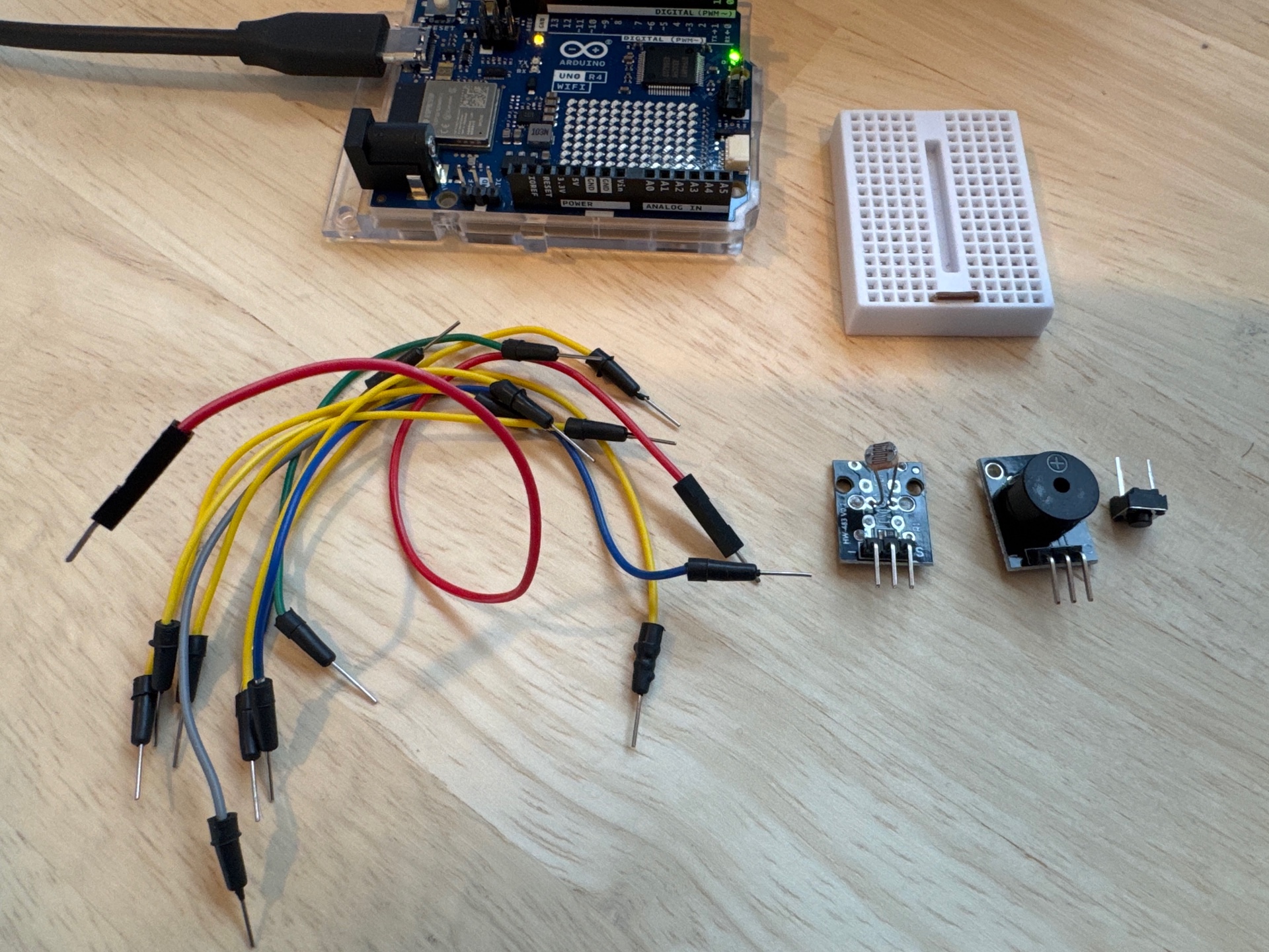
We've put together a simple hardware kit to get you started. It includes:
- An Arduino board (e.g., Arduino Uno R4)
- A small breadboard for prototyping circuits
- Jumper wires
- A push button
- A light sensor (LDR)
- A piezo buzzer
Getting Started with Arduino
In this demo we're using the Arduino Uno R4 but any Arduino board will do. Download the Arduino IDE and install it on your computer. The IDE is where you'll write and upload your code to the Arduino board. Use a USB-C cable to connect the board to your computer.
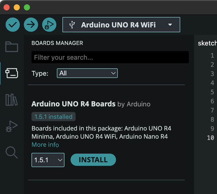
If you're working with the UNO R4 WiFi, make sure to install the necessary boards in the Arduino software. In the sidebar, click the "boards" icon (second icon from the top), search for "UNO R4" and click "Install".
Example 1: Blinking an LED
Conceptual principle: Digital outputs have only two states: HIGH (5V) or LOW (0V). This binary nature is the foundation of all digital electronics.
Here is the first bit of code we will write to have the LED blink on and off. Type the code (don't copy paste) to understand what's going on. Code after // are comments to explain the code; the Arduino ignores them.
// The setup function runs once when you press reset or power the board
void setup() {
  pinMode(13, OUTPUT);  // Configure pin 13 as output
}

// The loop function runs over and over again forever
void loop() {
  digitalWrite(13, HIGH);  // Turn LED on
  delay(1000);             // Wait 1 second
  digitalWrite(13, LOW);   // Turn LED off
  delay(1000);             // Wait 1 second
}
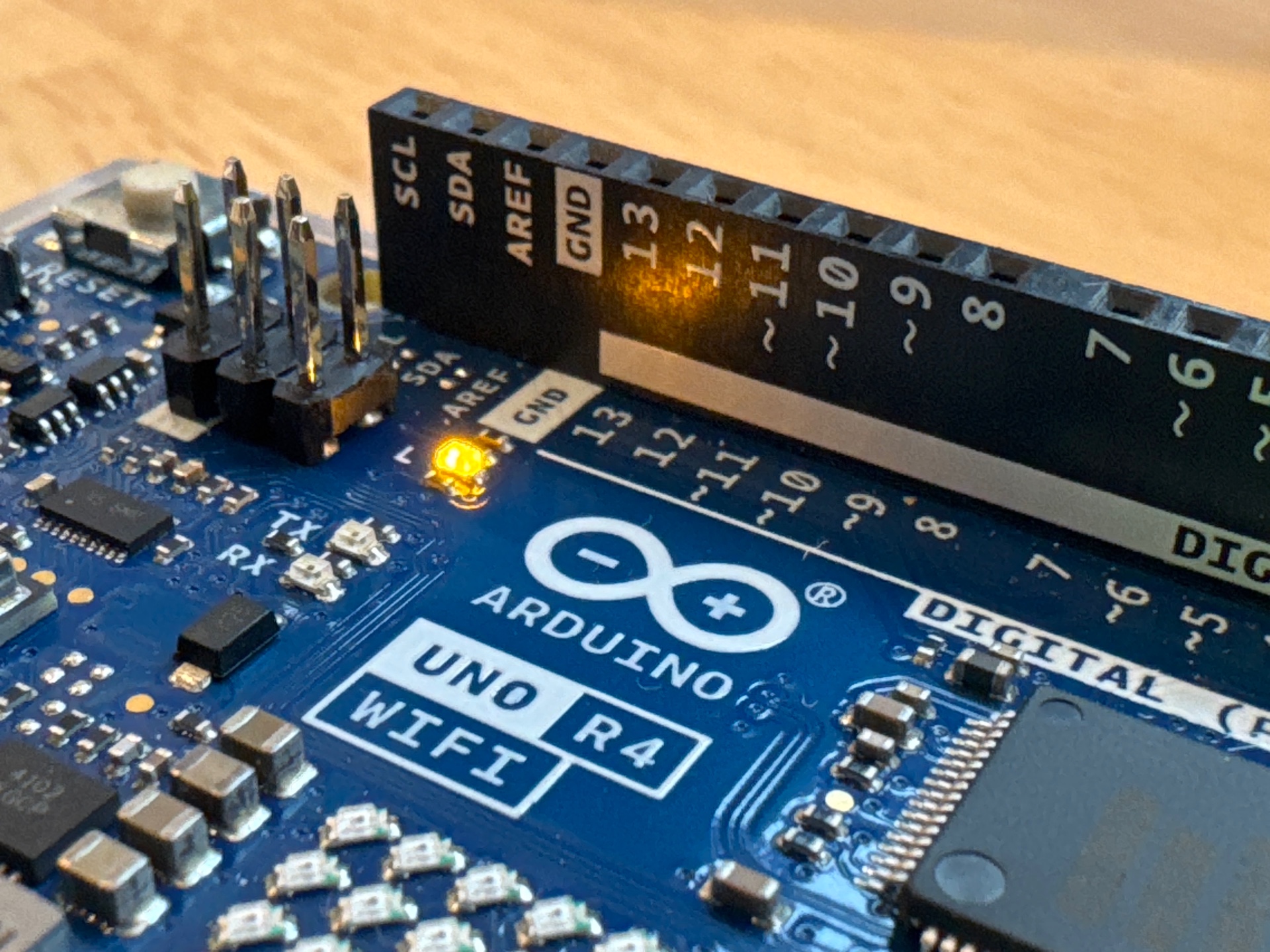
Write this code in the Arduino IDE, then hit the upload button (right arrow icon). The builtin LED should start blinking on and off every second.
Important: Pay attention to the exact detail of the code! Every semicolon, bracket and uppercase/lowercase letters have to be exactly right or it will give errors.
Key insight: The setup code runs once when the Arduino is powered on or reset, configuring pin 13 as an output. The loop code runs repeatedly, turning the LED on and off with a one-second delay in between. The blinking pattern emerges from the repetition of the on/off/delay loop structure.
Example 2: Tone Generator
Conceptual principle: The tone() function generates a square wave at a specific frequency. Sound is vibration: faster vibrations create higher pitches. The piezo speaker converts electrical oscillation into physical membrane movement.
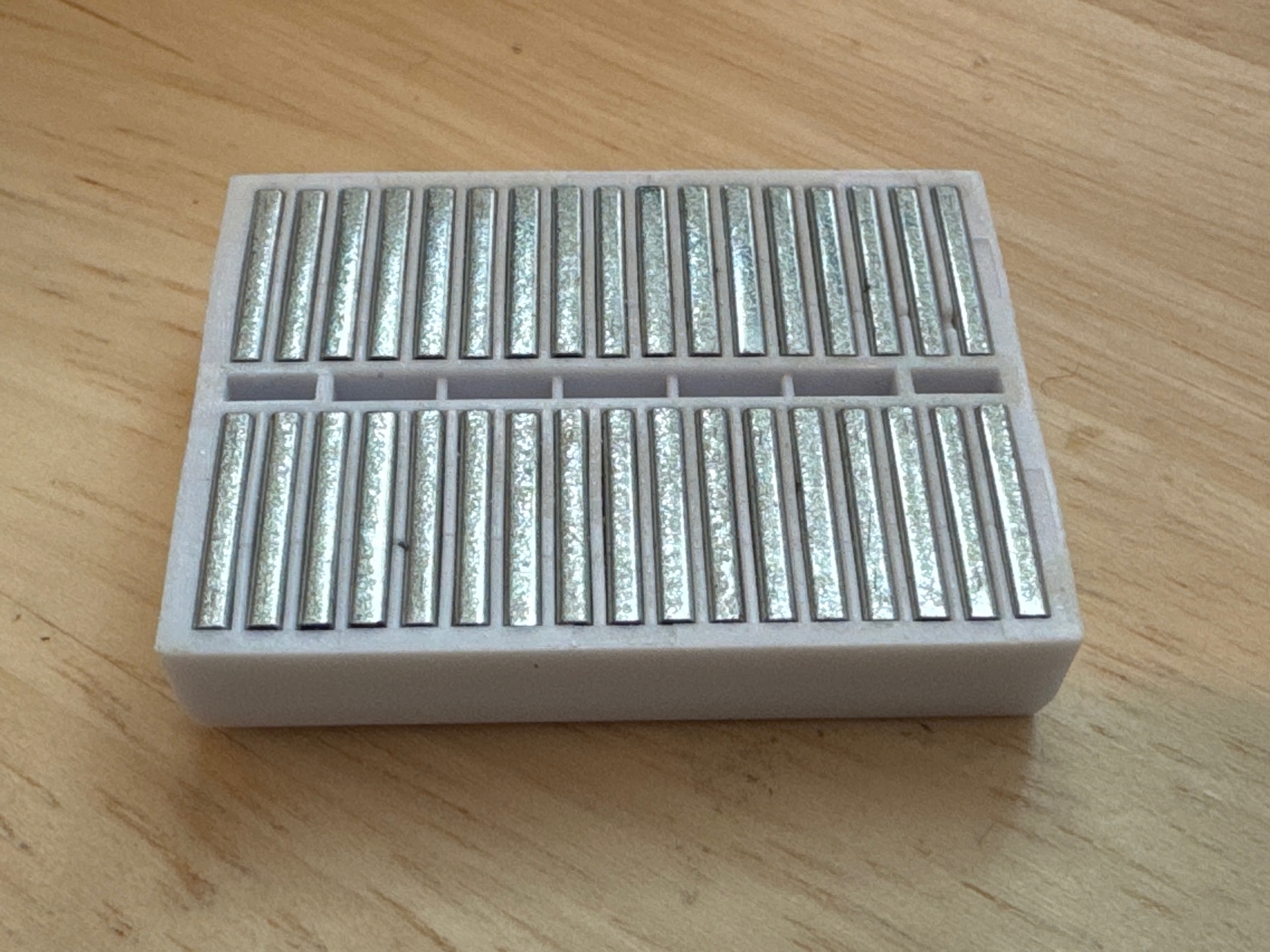
We'll use the breadboard for this. The breadboard has internal wires that connect the columns of the breadboard together. You can see this on the back of the breadboard:
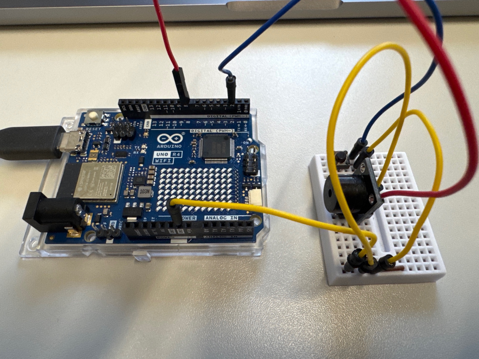
We'll first create a "ground rail": a row of pins that are all connected to ground (GND) on the Arduino. This makes it easier to connect multiple components to ground. Always use a consistent color for ground; I'm using yellow here:
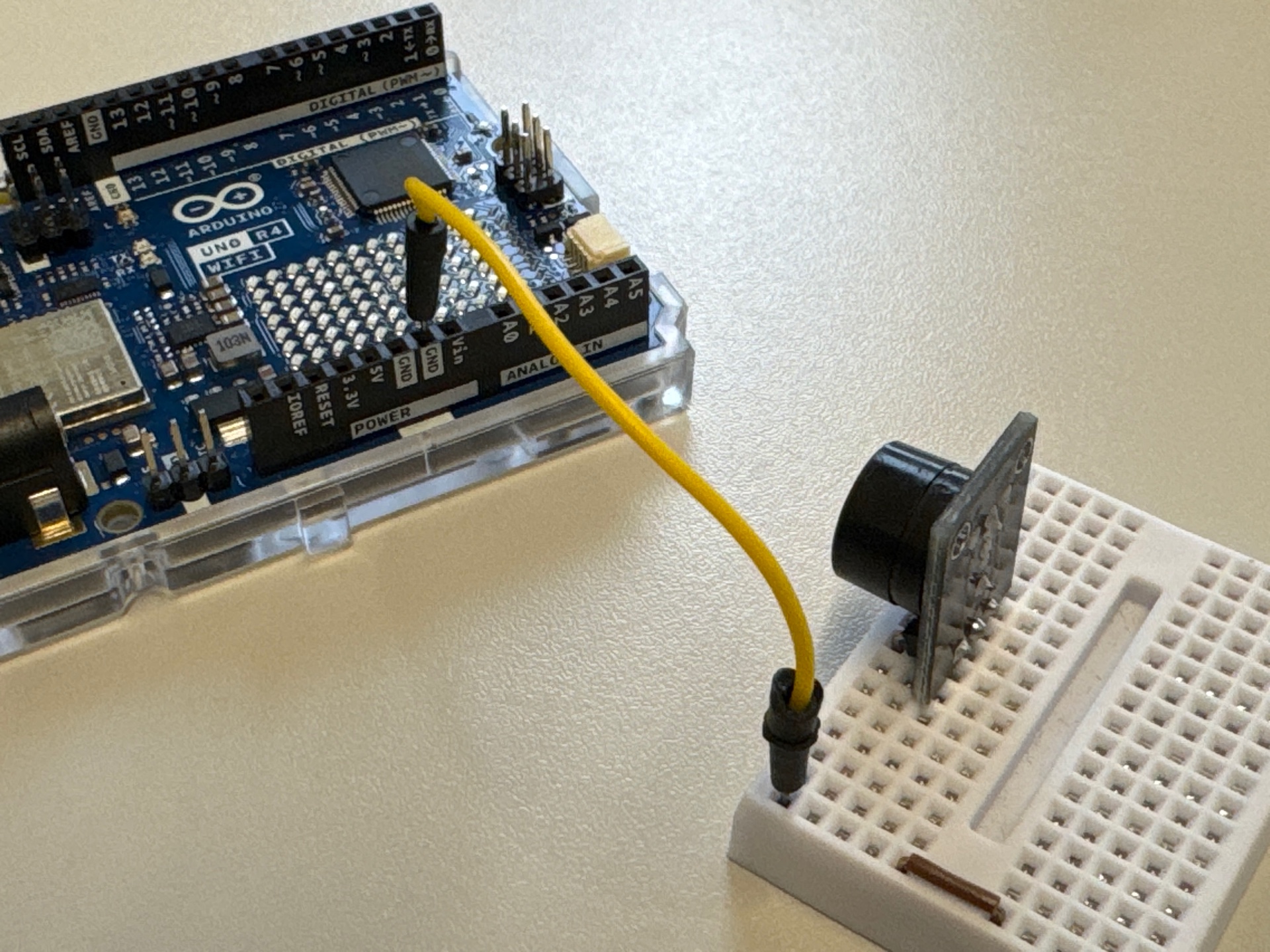
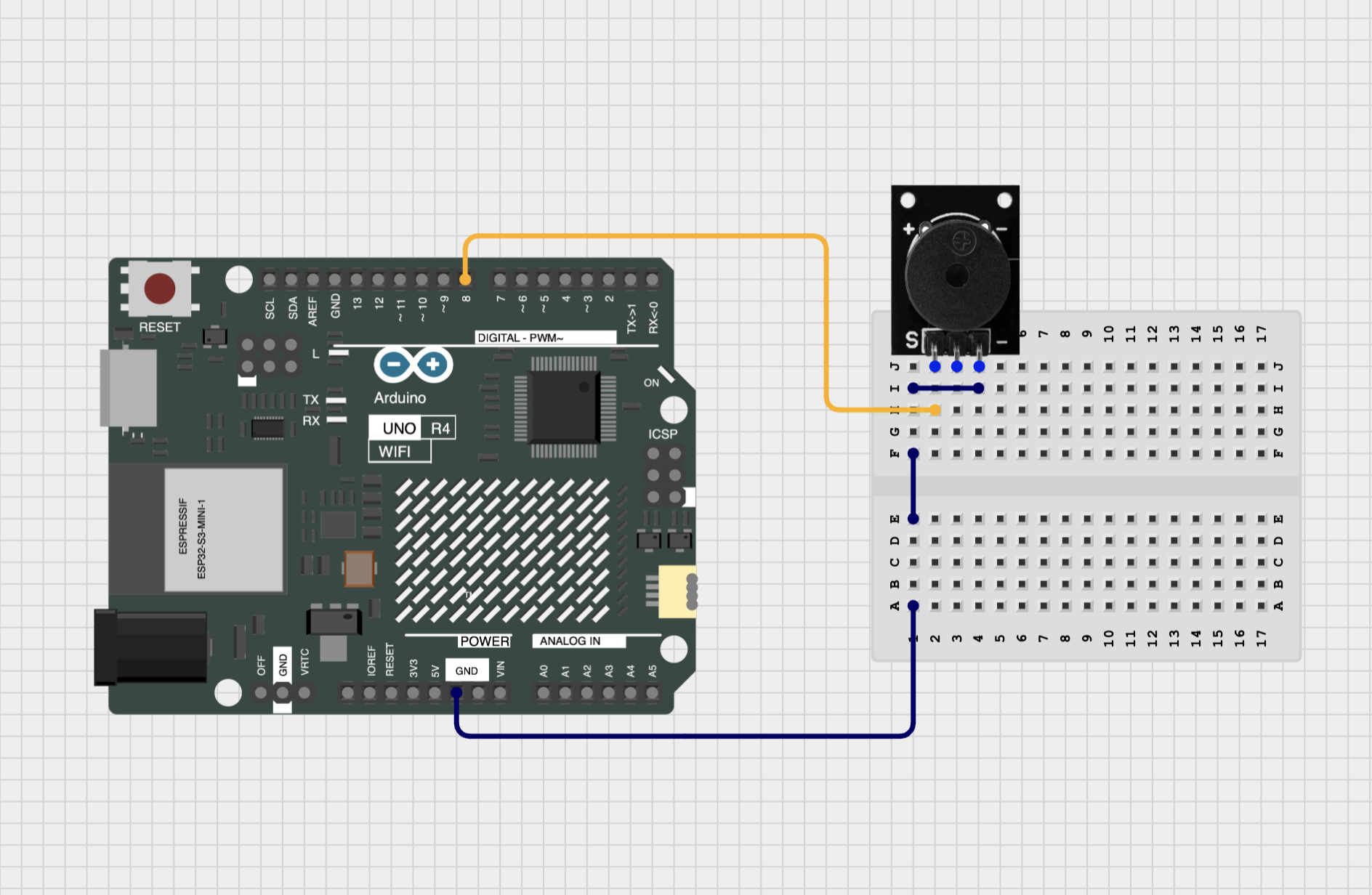
You see that I've already plugged in the piezo buzzer. Its location doesn't really matter; I just have it facing outwards. The buzzer needs two pins to connect: the - pin (negative) will connect to ground and the S pin (signal) will connect to port 8 on the Arduino. The middle pin is not used.
Connect the wires like so:
- From the GND pin on the Arduino to the ground rail (first column) on the breadboard (this should already be there).
- From the GND rail on the breadboard to the
-pin of the piezzo buzzer. - From pin 8 on the Arduino to the
Spin of the piezzo buzzer.
It should look like this:
Use the following code:
const int buzzerPin = 8;

void setup() {
  pinMode(buzzerPin, OUTPUT);
}

void loop() {
  tone(buzzerPin, 440);  // Play A4 note (440 Hz)
  delay(1000);           // Wait 1 second
  noTone(buzzerPin);     // Silence
  delay(1000);           // Wait 1 second
}
Key insight: Just like the LED, the code runs into a loop, turning the tone on and off every second. The tone() function generates a square wave at 440 Hz (the pitch of A4) when called, and noTone() stops the sound.
Try this: Change the frequency in the tone() function to other values, like 523 (C5), 587 (D5), or 659 (E5). You can find a list of frequencies for musical notes here. Make a simple melody by adding multiple lines with frequencies (each one followed by a delay). Shorten the delay times to make the melody go faster. What happens if the delays are very short, below 10 milliseconds?
How Electricity Flows
Electricity flows in a loop, from the positive pins (the numbered pins, or the Arduino's 5V pin), through the components (like the piezo buzzer), and back to ground (GND). The Arduino controls the flow of electricity (making the sound play) by either sending a signal (tone) or stopping the signal (noTone).
Example 3: Button-Controlled Tone
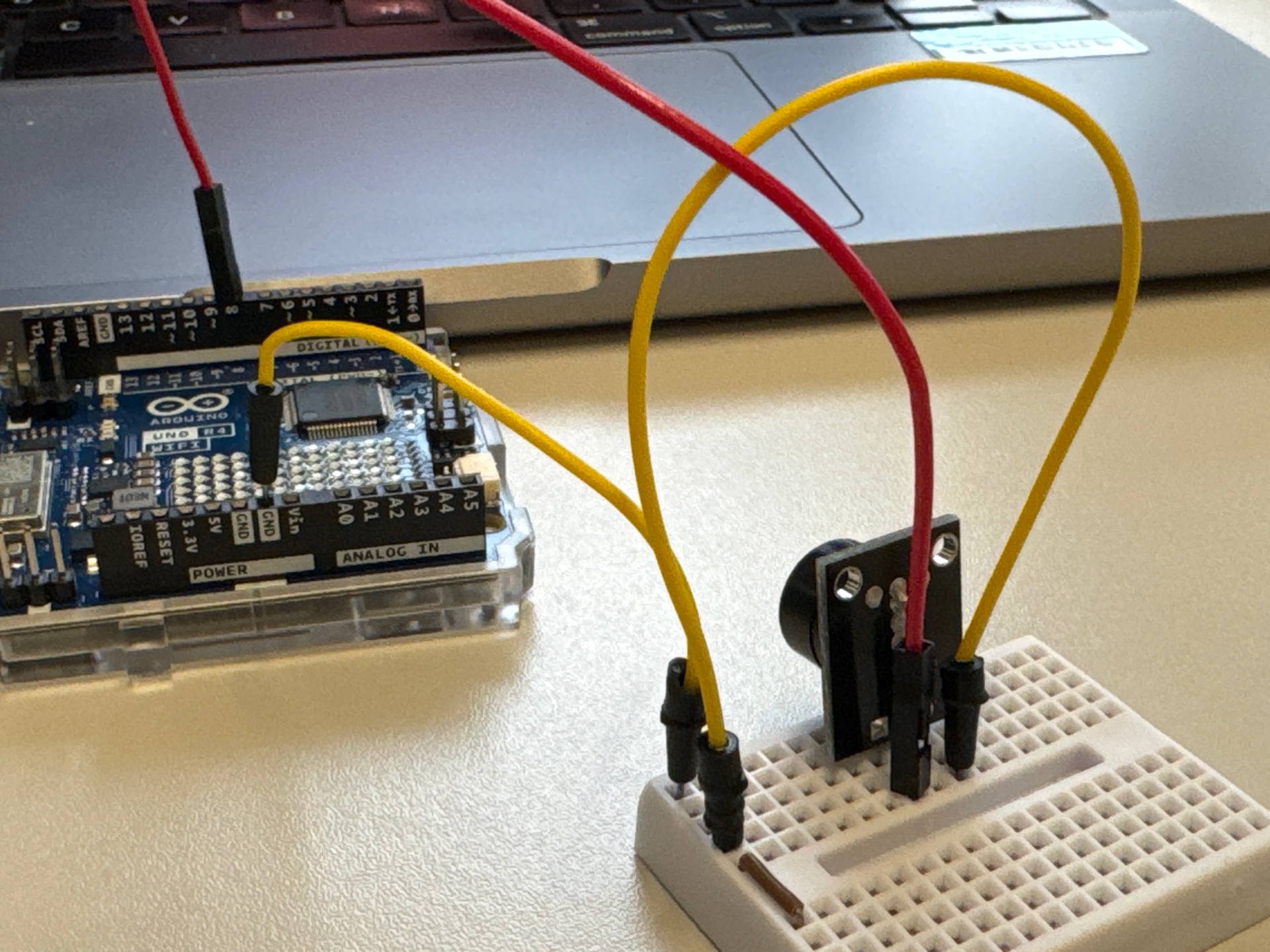
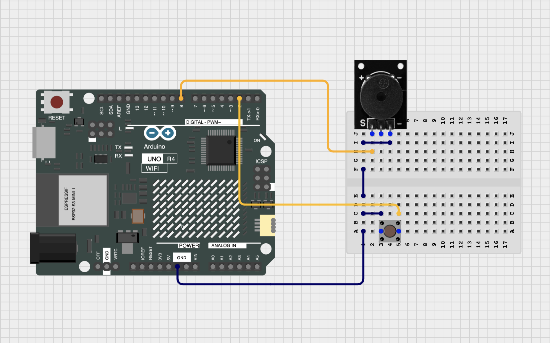
Now we'll also add a button to control when the tone plays.
Then connect wires (in italic are the wires that are already there from the previous example):
- From the GND pin on the Arduino to the ground rail (first column) on the breadboard.
- From the GND rail on the breadboard to the
-pin of the piezzo buzzer. - From pin 8 on the Arduino to the
Spin of the piezzo buzzer. - From the GND rail on the breadboard to one leg of the button.
- From pin 2 on the Arduino (Digital 2) to the other leg of the button.
It should look like this:
Use the following code:
const int buttonPin = 2;  // Button connected to digital pin 2
const int buzzerPin = 8;  // Buzzer connected to digital pin 8

void setup() {
  pinMode(buttonPin, INPUT_PULLUP);  // Internal resistor pulls pin HIGH
  pinMode(buzzerPin, OUTPUT);
}

void loop() {
  if (digitalRead(buttonPin) == LOW) {  // Button pressed (connects to ground)
    tone(buzzerPin, 440);               // Play A4 note (440 Hz)
  } else {
    noTone(buzzerPin);  // Silence
  }
}
Key insight: The button uses an internal pull-up resistor, so when not pressed, the pin reads HIGH. Pressing the button connects it to GND, making it read LOW. The tone() function generates a square wave at 440 Hz (the pitch of A4) when the button is pressed, and noTone() stops the sound when released. The interaction emerges from the continuous checking of the button state in the loop.
Example 4: On-Off Tone with Button
All examples before didn't use "state"; the tone played as long as the button was pressed. Now let's make it so that pressing the button toggles the tone on and off. For that, we need to keep track of the state of the buzzer (on or off) in a variable.
Important detail: we want to trigger the change of state at the moment the button is pressed (called the "rising edge" of the button press), otherwise the state would change continuously while the button is held down. Since many (thousands!) of loops run while the button is held down, the state would change very fast and unpredictably. We want to detect the exact moment the button is pressed.
const int buttonPin = 2;
const int buzzerPin = 8;

bool buzzerState = false; // Keep track of whether the buzzer is on or off
bool lastButtonState = HIGH; // Previous state of the button

void setup() {
    pinMode(buttonPin, INPUT_PULLUP);  // Internal resistor pulls pin HIGH
    pinMode(buzzerPin, OUTPUT);
}

void loop() {
    bool currentButtonState = digitalRead(buttonPin);

    // Check for button press (rising edge)
    if (lastButtonState == HIGH && currentButtonState == LOW) {
        buzzerState = !buzzerState; // Toggle buzzer state
    }

    // Update the buzzer based on its state
    if (buzzerState) {
        tone(buzzerPin, 440);  // Play A4 note (440 Hz)
    } else {
        noTone(buzzerPin);     // Silence
    }

    lastButtonState = currentButtonState; // Save the current state for next loop
}
Key insight: We use two boolean variables: buzzerState to track whether the buzzer is on or off, and lastButtonState to remember the previous state of the button. In each loop, we read the current button state and check if it has changed from HIGH to LOW (indicating a button press). If so, we toggle the buzzerState. The buzzer plays or stops based on the value of buzzerState. This creates a toggle effect where each button press changes the buzzer's state.
Example 5: Siren Sounds
Now that we have a basic button-to-sound interaction, let's make it more interesting by creating a siren sound that changes pitch over time while the button is pressed.
const int buttonPin = 2;
const int buzzerPin = 8;

void setup() {
    pinMode(buzzerPin, OUTPUT);
    pinMode(buttonPin, INPUT_PULLUP);
}

void loop() {
    if (digitalRead(buttonPin) == LOW) { // Button pressed
        playSiren();
    } else {
        noTone(buzzerPin);
    }
}

void playSiren() {
    for (int freq = 400; freq < 800; freq += 2) {
        tone(buzzerPin, freq);
        delay(10);
    }
}
Key insight: The playSiren() function creates a rising pitch effect by gradually increasing the frequency from 400 Hz to 800 Hz in small increments. The delay(10) controls how quickly the pitch changes, creating a smooth siren sound. We use a for loop to repeatedly call tone() with increasing frequencies.
Variation 5.1: Random Siren
A variation on the siren is to play a random frequency sound while the buzzer is held down. For this we need a way to generate random numbers, and also change the playSiren function:
void setup() {
    // Add these lines below the other lines in setup:

    // Seed random number generator with noise from an unconnected pin
    randomSeed(analogRead(0));
}

// Replace playSiren with this code:
void playSiren() {
    // Play 20 random tones
    for (int i = 0; i < 20; i++) {
        int freq = random(200, 1000); // Random frequency between 200 and 1000 Hz
        tone(buzzerPin, freq);
        delay(50); // Short delay to allow the sound to be heard
    }
    noTone(buzzerPin); // Stop the tone after the loop
    delay(200); // Short pause before the next siren
}
Example 6: Playing a Melody
Now let's create a simple melody that plays when the button is pressed. We'll define the notes in an "array" (a fancy word for a list), then play them in sequence.
const int buttonPin = 2; // Button connected to digital pin 2
const int buzzerPin = 8; // Buzzer connected to digital pin 8
const int noteLength = 130; // Duration of each note in milliseconds

// Frequencies of each note of the melody
// This is Steve Reich's "Piano Phase"
int melody[] = {
  330, 370, 494, 554,   // E4, F#4, B4, C#5
  587, 370, 330, 554,   // D5, F#4, E4, C#5
  494, 370, 587, 554    // B4, F#4, D5, C#5
};

void setup() {
    pinMode(buzzerPin, OUTPUT);
    pinMode(buttonPin, INPUT_PULLUP);
}

void loop() {
    if (digitalRead(buttonPin) == LOW) { // Button pressed
        playMelody();
    } else {
        noTone(buzzerPin);
    }
}

void playMelody() {
    // This calculates the length of the array
    const int length = sizeof(melody) / sizeof(melody[0]);
    for (int i = 0; i < length; i++) {
      tone(buzzerPin, melody[i], noteLength * 0.2); // Play the note for 20% of its duration
      delay(noteLength); // Wait for the full note duration before playing the next one
    }
}
Key insight: The melody is defined as an array (a list) of frequencies corresponding to musical notes. The playMelody() function iterates through the array, playing each note for a specified duration followed by a pause. This creates a simple melody that plays when the button is pressed.
Try this: Modify the melody array to create your own melody. You can change the frequencies to other notes, add more notes, or remove some. Experiment with the noteLength variable to make the melody play faster or slower.
Variation 6.1: Beat Sequencer
Instead of storing frequencies, we can store a pattern of 1s and 0s to create a simple beat sequencer. A 1 means "play a sound" and a 0 means "silence". This is a common pattern in drum machines and sequencers.
const int buttonPin = 2;
const int buzzerPin = 8;
const int stepDuration = 150; // Duration of each step in milliseconds

// Beat pattern: 1 = sound, 0 = silence
// This is Steve Reich's "Clapping Music" pattern
int beatPattern[] = {
  1, 1, 1, 0,   // Three claps, rest
  1, 1, 0, 1,   // Two claps, rest, one clap
  0, 1, 1, 0    // Rest, two claps, rest
};

void setup() {
    pinMode(buzzerPin, OUTPUT);
    pinMode(buttonPin, INPUT_PULLUP);
}

void loop() {
    if (digitalRead(buttonPin) == LOW) { // Button pressed
        playBeat();
    } else {
        noTone(buzzerPin);
    }
}

void playBeat() {
    int length = sizeof(beatPattern) / sizeof(beatPattern[0]);
    for (int i = 0; i < length; i++) {
      if (beatPattern[i] == 1) {
        tone(buzzerPin, 200, stepDuration / 2); // Play for half a step
        delay(stepDuration);                    // Wait full step
      } else {
        delay(stepDuration);                    // Silence for full step
     }
    }
}
Key insight: Instead of storing musical notes, we store a rhythm pattern using 1s and 0s. The playBeat() function reads through the pattern, playing a tone when it encounters a 1 and staying silent when it encounters a 0. This creates a percussive rhythm that repeats when the button is held down.
Try this: Modify the beatPattern array to create your own rhythm. Try making it longer or shorter. Change the stepDuration to make the beat faster or slower. You can also change the frequency (currently 200 Hz) to create different timbres.
Example 7: Measuring Light with a Photoresistor
A photoresistor (or LDR - Light Dependent Resistor) changes its resistance (the amount of current that can flow through it) based on the amount of light hitting it. More light means less resistance, allowing more current to flow. We can use this property to measure light levels.
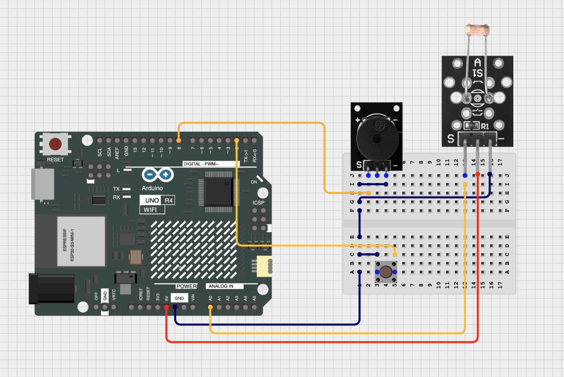
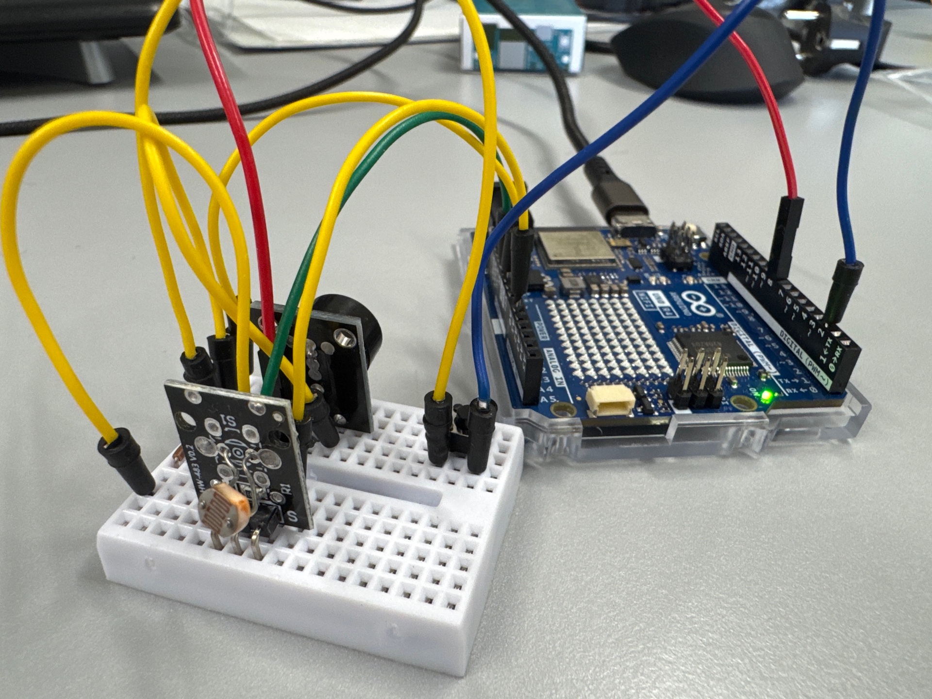
Hardware: We'll need to add the photoresistor to our breadboard:
- Connect the
-leg of the photoresistor to the GND rail 5V on the Arduino - Connect the middle leg to 5V on the Arduino
- Connect the
Sleg to Analog pin A0.
It should look like this:
We're just going to read the value from the photoresistor and print it on our computer. For that, we'll use the Serial Monitor in the Arduino IDE: it's a way for your Arduino to "talk back" to your computer.
const int lightPin = A0; // Photoresistor connected to analog pin A0

void setup() {
    Serial.begin(9600); // Start serial communication at 9600 baud
    pinMode(lightPin, INPUT);
}

void loop() {
    int lightValue = analogRead(lightPin); // Read the light level (0-1023)
    Serial.println(lightValue); // Print the value to the Serial Monitor
    delay(100); // Wait a bit before the next reading
}
Upload the code, then open the Serial Monitor (the magnifying glass icon in the top right of the Arduino IDE). You should see numbers between 0 and 1023 being printed. These numbers represent the light level detected by the photoresistor: 0 means complete darkness, and 1023 means very bright light.
Open the Serial Plotter (next to the Serial Monitor icon) to see a graph of the light levels over time. Try covering the photoresistor with your hand or shining a light on it to see how the values change. Note the range of values (minimum and maximum) you get in your environment.
Key insight: The photoresistor acts as a variable resistor, changing its resistance based on light levels. The Arduino reads this change as an analog value between 0 and 1023, which we can use to measure the intensity of light in the environment.
Example 8: Tone Controlled by Light
Now that we can measure light levels, let's use that data to control the pitch of a tone. The brighter the light, the higher the pitch. To convert the light value (0-1023) to a frequency range (e.g., 200-1000 Hz), we'll use the map() function.
const int lightPin = A0;  // Photoresistor connected to analog pin A0
const int buttonPin = 2; // Button is connected to digital pin 2
const int buzzerPin = 8;  // Buzzer connected to digital pin 8

void setup() {
  pinMode(lightPin, INPUT);
  pinMode(buttonPin, INPUT_PULLUP);
  pinMode(buzzerPin, OUTPUT);

  // We'll be plotting the light level and frequency
  Serial.begin(9600);  // Start serial communication at 9600 baud
}

void loop() {
  // Only play tones when the button is pressed
  if (digitalRead(buttonPin) == LOW) {      // Button pressed
    int lightLevel = analogRead(lightPin);  // Read the light level (0-1023)
    Serial.print(lightLevel);               // Print the light level (use "print" instead of "println" to stay on the same line)
    Serial.print(", ");                     // Print a comma to separate the light level and frequency

    // Map the light value (0-1023) to a frequency range (200-1000 Hz)
    // Note that we invert the range: more light = higher frequency
    int frequency = map(lightLevel, 1023, 0, 200, 1000);
    Serial.println(frequency);  // Print the frequency (use "println" here to go to the next line);

    tone(buzzerPin, frequency);  // Play tone at the mapped frequency
  } else {
    // If button is released, don't play a tone
    noTone(buzzerPin);
  }
  delay(100);  // Short delay to allow the sound to be heard
}
Key insight: The map() function takes the light value (0-1023) and converts it to a frequency range (200-1000 Hz). The tone() function then plays a sound at that frequency. As the light level changes, the pitch of the sound changes accordingly, creating an interactive experience where light controls sound.
Example 9: Light-Controlled Melody
Now let's take it a step further and use the light level to control which note of a melody is played. We'll use the same melody array from Example 5, but this time, the light level determines how fast the melody plays.
const int lightPin = A0;         // Photoresistor connected to analog pin A0
const int buttonPin = 2;         // Button is connected to digital pin 2
const int buzzerPin = 8;         // Buzzer connected to digital pin 8

int melodyLength = 0;
int noteIndex = 0;

// Frequencies of each note of the melody
int melody[] = {
  330, 370, 494, 554,  // E4, F#4, B4, C#5
  587, 370, 330, 554,  // D5, F#4, E4, C#5
  494, 370, 587, 554   // B4, F#4, D5, C#5
};

void setup() {
  pinMode(lightPin, INPUT);
  pinMode(buttonPin, INPUT_PULLUP);
  pinMode(buzzerPin, OUTPUT);

  // We'll be plotting the light level
  Serial.begin(9600);  // Start serial communication at 9600 baud

  // Store the length of the melody (we'll need it later)
  melodyLength = sizeof(melody) / sizeof(melody[0]);
}

void loop() {
  // Only play tones when the button is pressed
  if (digitalRead(buttonPin) == LOW) {      // Button pressed
    int lightLevel = analogRead(lightPin);  // Read the light level (0-1023)
    Serial.println(lightLevel);             // Print out the light level
    playNote(lightLevel);                   // Pass light value to control note speed
  } else {
    noTone(buzzerPin);
  }
}

// We're playing here note-by-note, since we want changes in light level to have a direct effect
// on the next note we're playing, and not have to wait until the melody restarts.
void playNote(int lightLevel) {
  // Map light value (0-1023) to note length (ms)
  int noteLength = map(lightLevel, 0, 1023, 20, 500);

  // Play the note for 40% of noteLength
  tone(buzzerPin, melody[noteIndex], noteLength * 0.4);
  delay(noteLength);  // Total note time including "pause"

  // Go to the next note
  noteIndex++;
  // If our index would be larger than the amount of notes, reset
  if (noteIndex >= melodyLength) {
    noteIndex = 0;
  }
}
Variation 9.1: Light-Controlled Octaves
A variation on the light-controlled melody is to change the octave of the melody based on the light level. We'll use the same melody array, but this time, we'll multiply the frequency of each note by a factor that changes with the light level.
// Just replace the playNote function:
void playNote(int lightLevel) {
  // Map the light value (0-1023) to an octave factor (1-4)
  float octaveFactor = map(lightLevel, 0, 1023, 4, 1);
  int noteLength = 200; // Fixed total note length
  int frequency = melody[noteIndex] * octaveFactor;  // Adjust octave

  // Play the note for 40% of noteLength
  tone(buzzerPin, frequency, noteLength * 0.4);

  // Wait total note time including pause
  delay(noteLength);

  // Go to the next note
  noteIndex++;
  // If our index would be larger than the amount of notes, reset
  if (noteIndex >= melodyLength) {
    noteIndex = 0;
  }
}
Example projects
Example projects can be found on our Notion
Conclusion
Arduino is a powerful tool for artists to create interactive and engaging installations. By understanding the basics of physical computing, inputs and outputs, and how to write simple code, you can start building your own projects. Experiment with different sensors and actuators, and let your creativity guide you!
All code examples are available for download: arduino-for-artists.zip